Attaching Meters
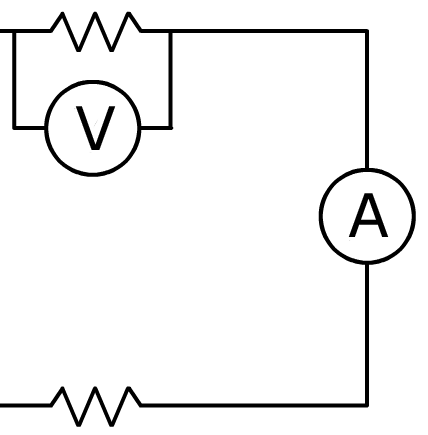
Correctly placing ammeters and voltmeters to measure circuit quantities
|
Show Me
The Physics
School blocks YouTube?
Circuit Challenge
Show Me
The Physics
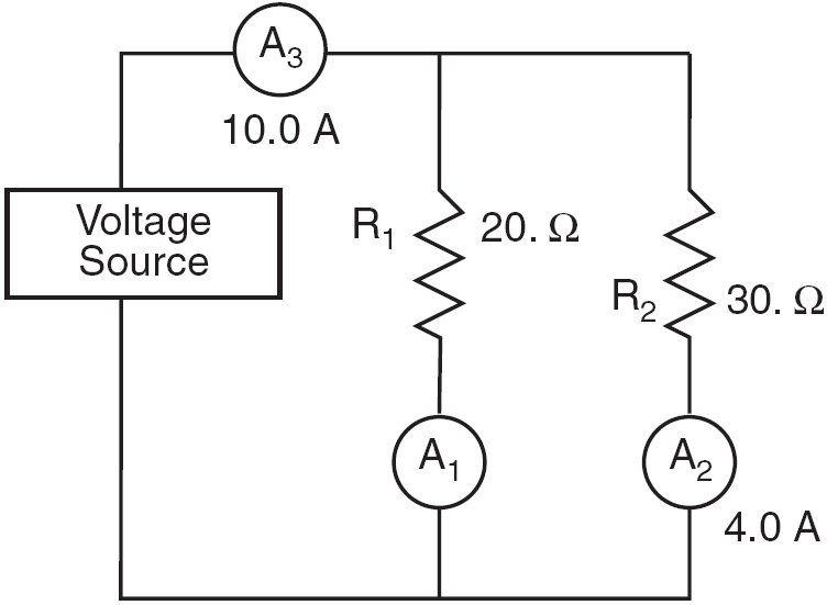
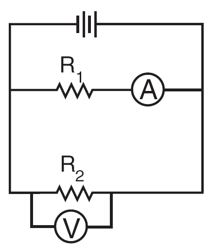
a) I1 = ?
IT = I1 + I2
10.0 A = I1 + 4.0 A
I1 = 6.0 A
b) VT = ?
VT = V1 = V2
V2 = IR
= 4.0 A (30. ohms)
V2 = 120 V
So,
VT = 120 V
Learning-Connections Clipart
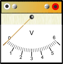
Voltmeters
Ammeters
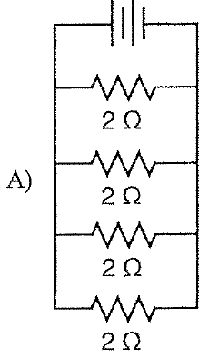
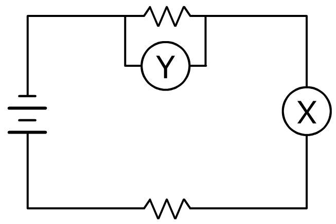
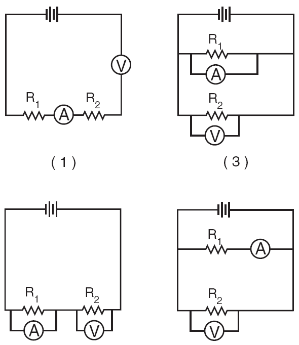
Which circuit is correct?
June 2006
Attaching Meters - Flash showmethephysics.com
Dorling Kindersley Books
Flash Animations for Physics
Choice 4
|
|||||||||||||||||



 Task





Check Your Understanding
5 quick questions — pick an answer to see if you’re right.
1. How should an ammeter be connected to measure the current through a resistor?
2. How should a voltmeter be connected to measure the potential difference across a resistor?
3. A voltmeter measures potential difference. Potential difference is the:
4. In a two-branch parallel circuit, the total current is 10.0 A and one branch carries 4.0 A. What does the other branch carry?
5. In a parallel circuit, a 30. Ω branch carries 4.0 A. What is the source voltage?
Measuring a Circuit Correctly
A student builds a circuit with a 12-V battery and two resistors, 4.0 Ω and 8.0 Ω, in series. She wants to measure the current through the circuit and the potential difference across the 8.0-Ω resistor.
How should the meters be connected?
▶ Want a challenge? Open 6 more Regents-style questions (harder · mixed formats)
Challenge score: 0 / 6
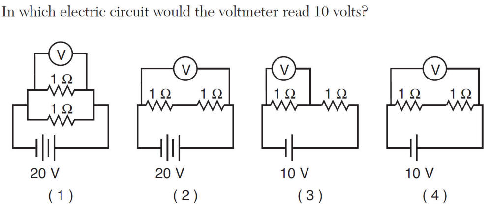
C1. A voltmeter could be connected in several places. Place a check mark in two boxes to indicate the placements where the voltmeter would read 12 V.
C2. Ideally, what resistance should each meter have so it does not change the circuit?
C3. Substitute numerical values into a mathematical representation that can be used to determine the current the ammeter should read. Then calculate the current.
C4. A student makes the following claim.
Place a check mark in either the Support or Refute box. Justify your response using a mathematical relationship.
C5. The student accidentally connects the ammeter in parallel across the battery. What is the likely result?
C6. The student’s cheap voltmeter has an internal resistance of only 8.0 Ω. Describe how connecting this meter across the 8.0-Ω resistor changes the circuit, and determine what the meter would actually read.