Fill in the Blank Notes


Total Resistance in Parallel Circuits lesson illustration


What kind of circuit has multiple current paths?

APlus Physics YouTube Channel


Parallel Circuit Practice Problems

APlus Physics YouTube Channel


Total Resistance Parallel Circuit


Total Resistance in Parallel Circuits lesson illustration

Circuits & Total Resistance - Flash

[ HTML5 ]

showmethephysics.com


Total Resistance in Parallel Circuits lesson illustration

Learning-Connections Clipart


Deriving an Equation for Total Resistance


Since IT = I1 + I2 + I3 + I4 +……

Then …

VT = V1 + V2 + V3
RT R1 R2 R3


On Reference Table

1 = 1 + 1 + 1
RT R1 R2 R3

Total Resistance in Parallel Circuits lesson illustrationTotal Resistance in Parallel Circuits lesson illustrationTotal Resistance in Parallel Circuits lesson illustrationTotal Resistance in Parallel Circuits lesson illustrationTotal Resistance in Parallel Circuits lesson illustration


RT - Total Resistance

A.K.A.

"Equivalent Resistance"
"Combined Resistance"
"Effective Resistance"


Total Resistance in Parallel Circuits lesson illustrationTotal Resistance in Parallel Circuits lesson illustrationTotal Resistance in Parallel Circuits lesson illustrationTotal Resistance in Parallel Circuits lesson illustrationTotal Resistance in Parallel Circuits lesson illustration


Ex 3) Find the total resistance for 3 resistors of 2.0 ohms, 5.0 ohms and 2.0 ohms connected in parallel.


1 = 1 + 1 + 1
RT R1 R2 R3

1 = 1 + 1 + 1
RT 2.0 Ω 5.0 Ω 2.0 Ω


Find common denominator and solve 

1/RT = 5/10 Ω + 2/10 Ω + 5/10 Ω


1/RT = (5 + 2 + 5)/10


1/RT = 12/10


RT = 10/12 ohms


RT = .83 ohms


Total Resistance in Parallel Circuits lesson illustrationTotal Resistance in Parallel Circuits lesson illustrationTotal Resistance in Parallel Circuits lesson illustrationTotal Resistance in Parallel Circuits lesson illustrationTotal Resistance in Parallel Circuits lesson illustration


** The more resistors
 connected in parallel
the smaller the total resistance!!!


Total Resistance in Parallel Circuits lesson illustration

Circuits & Total Resistance

[ HTML5 ]
St. Mary's H.S.


Why?


Every time you add a resistor in parallel,


you add another branch for current,


so you create more current.


This reduces the total R. 


Total Resistance in Parallel Circuits lesson illustrationTotal Resistance in Parallel Circuits lesson illustrationTotal Resistance in Parallel Circuits lesson illustrationTotal Resistance in Parallel Circuits lesson illustrationTotal Resistance in Parallel Circuits lesson illustration


Total Resistance Equation #2
for parallel circuit


RT = VT/IT


Total Resistance in Parallel Circuits lesson illustrationTotal Resistance in Parallel Circuits lesson illustrationTotal Resistance in Parallel Circuits lesson illustrationTotal Resistance in Parallel Circuits lesson illustrationTotal Resistance in Parallel Circuits lesson illustration


Ex 4) Resistors of 3.0 Ω, 6.0 Ω, 9.0 Ω are connected in parallel.


Find combined R


1 = 1 + 1 + 1
RT R1 R2 R3

1/RT =


1/3.0 Ω + 1/6.0 Ω + 1/9.0 Ω


(common denominator, 18)


 = (6.0 + 3.0 + 2.0)/18. = 11./18.


RT = 18./11. Ω


 = 1.6 ohms


Total Resistance in Parallel Circuits lesson illustrationTotal Resistance in Parallel Circuits lesson illustrationTotal Resistance in Parallel Circuits lesson illustrationTotal Resistance in Parallel Circuits lesson illustrationTotal Resistance in Parallel Circuits lesson illustration


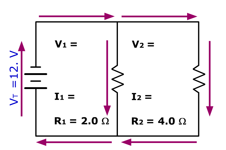
Ex. 5)

Total Resistance in Parallel Circuits lesson illustration

a) Find the equivalent resistance for this parallel circuit


1 = 1 + 1 + 1
RT R1 R2 R3


1/RT  = 1/2.0 Ω + 1/4.0 Ω


1/RT = 3.0 Ω/4.0 Ω


RT = 4.0 Ω/3.0 Ω


= 1.3 ohms


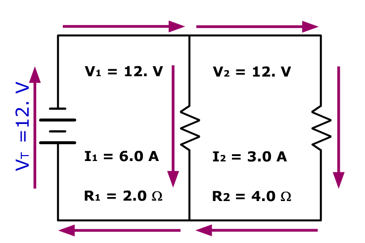
b) Find IT (Current coming out of the source)


Total Resistance in Parallel Circuits lesson illustration


VT  = ITRT


12. V = IT(1.3 ohms)


IT = 9.0 amps


Total Resistance in Parallel Circuits lesson illustration


c) Find the potential drop (V) across R1 & R2 


VT = V1 = V2 = V3


VT = V1 = V2 = 12V 


Total Resistance in Parallel Circuits lesson illustration


Check Your Understanding

5 quick questions — pick an answer to see if you’re right.

1. Which equation gives the total resistance of resistors in parallel?

2. A 3.0 Ω and a 6.0 Ω resistor are connected in parallel. What is the equivalent resistance?

3. A 12 V source is connected to a parallel circuit whose total resistance is 2.0 Ω. What is the total current?

4. Two 10. Ω resistors are in parallel. What is the total resistance?

5. A student adds another resistor in parallel and predicts the total resistance will increase. What really happens?

NYSSLS Regents Practice · Circuits · Equivalent Resistance

Two Heating Elements in Parallel

A space heater has two heating elements, 6.0 Ω and 3.0 Ω, connected in parallel across a 12-V source (a model of the real 120-V heater).

What is the equivalent resistance of the two elements?

▶ Want a challenge? Open 6 more Regents-style questions  (harder · mixed formats)

Challenge score: 0 / 6

Multiple choice

C1. Which statement is always true for resistors in parallel?

Substitute values

C2. Substitute numerical values into a mathematical representation that can be used to determine the total power produced by the heater model on the “high” setting (both elements on). Then calculate the power.

P = V2Req = ( V)2 Ω = W
Determine the value

C3. Determine the current in the 6.0-Ω heating element.

I = A
Support or Refute · Justify

C4. A student makes the following claim.

Claim: Adding the 3.0-Ω element in parallel with the 6.0-Ω element increases the total resistance of the heater, because there is more resistor material for the charge to pass through.

Place a check mark in either the Support or Refute box. Justify your response using a mathematical relationship.

Multiple choice

C5. Which change increases the equivalent resistance of a parallel circuit?

Constructed response

C6. An engineer suggests wiring the two elements in series instead of in parallel across the same 12-V source. Identify one benefit and one drawback of this design. Support your answer with a calculation.